|
 |
 |
 |
 |
 |
 |
||||||||||||
Lambretta Engine WorkGeneralLambretta |
Lambretta Series III GearboxA Lambretta Series 1-3 has a gearbox that is basically located almost in the rear wheel hub. There are many small differences between models, and this page shows a Series III gearbox removal and installation. Some tools and items you'll need:
This page also assumes that you have the chaincase off, the clutch removed, and the rear wheel removed.
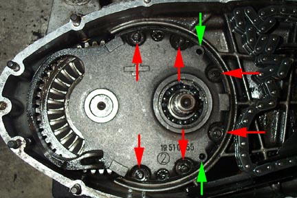
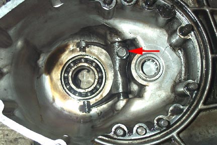
The first step is to remove the gearbox backplate. Use an 11mm socket to remove the six nuts arrowed with red and the six lock washers around the perimeter. Unfortunatley once these are removed the plate will not come off because it is a tight fit on the end of the gear cluster shaft. The solution is to use two 6mm bolts and insert them into the green arrowed holes above. Slowly and equally tighten each one to force the backplate away from the casing. Soon the backplate will be able to be lifted off exposing the gearbox parts inside.
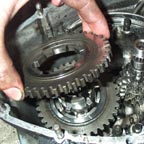
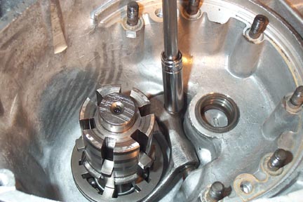
With the backplate out of the way you can gain access to the free gears and the gear cluster and selector spider. There is a single shim for the free gears which can be removed and kept for safe keeping (red arrow above). The one in the shot is very worn with a clear groove around the inside.
Now the free gears can be removed from the axle. Be sure to note which way each gear faces when you remove them as they need to go back in the same orientation. It is handy to stack them in the right way and put a zip tie through them to be sure they will go back the same way later. You may need to slightly rotate the gears on the shaft to allow them to be lifted off.
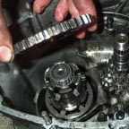
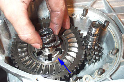
Remove the small gear cluster and watch out for a small shim where the green arrow is pointed. This may stick to the bearing in the casing or to the gear shaft. You can also remove the other caged bearing at the end of the free gear axle and the small end shim beneath it. Either renew these items or hold on to them for the rebuild. The gear spider is a little tricky to remove. I found that pulling up on it hard is a good way to remove it from the rear axle. Be warned that there is a single spring and two ball bearings which may shoot out from the interior of the shaft so use a rag to stop them shooting out. The actuating arm of the selector will stay in the casing for now.
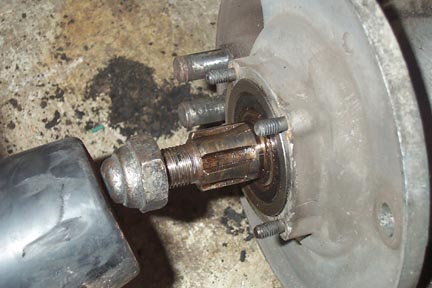
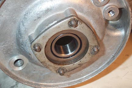
With the gear selector spider removed, the gear axle can be removed by banging it out of the rear bearing. I usually put an old nut on the axle to protect the threads from any damage. At this point you can also decide to replace the rear bearing and oil seal if you want to (I did). To remove the rear bearing, the four bearing retaining nuts, locknuts, thick metal retaining plate, and thin sheet metal spacer need to be removed from the rear hub area of the engine casing. Then the bearing and oil seal can be pounded out from inside the casing in the direction of the rear hub. I had my brake shoes off at the time the photo was taken but it is not required to remove them.
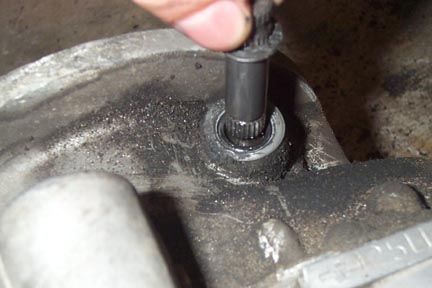
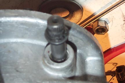
Remove the arrowed bolt with a 10mm socket which releases its grip on the gear selector splined shaft.
The gear actuator arm can only be removed from inside the casings by removing the external gear selector splined shaft. This exits the casing right by the rear wheel. Pull the splined shaft out of the internal actuating arm by lifting upwards and you should hear the actuator fall into the casing inside. Your actuator may be a two piece assembly like mine or a single piece as fitted to later models.
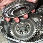
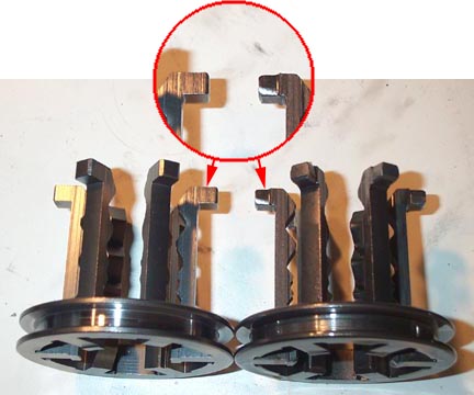
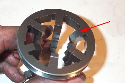
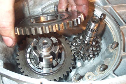
While you have the parts out and the gearbox open, you might as well replace all the items that wear and cause gear selector problems, or allow the bike to jump out of gear. Above is a shot of a new spider on the left and a used spider on the right. You can see the rounded over ends to the spider which can cause the bike to slip out of gear when riding. Also have a look at the contact points where the spider hits the free gears to see if each gear is in good condition. Now we'll start rebuilding the gearbox. I rebuilt mine into brand new casings and I replaced all shims, bearings, and the spider.
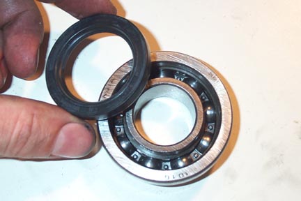
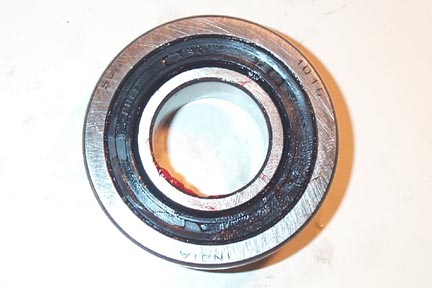
The first step is to replace the rear bearing. The bearing has an oil seal that prevents gearbox oil from leaking out into the rear hub and ruining the brake shoes. This seal goes into the stepped bearing on the side with the larger step (if you look at the bearing you'll see what I mean). The side with the circular spring in the lip faces the smaller side of the step (it faces towards the gearbox).
Put a little grease around the inside lip of the seal and push it into the bearing race. Once it is in properly the bearing will not spin as freely as it used to because of the friction. It should look like above. Now the bearing can be fit into the casing. It is especially important to be sure the bearing is set into the casing as far as it will go, although it will never be flush on the hub side. The reason for this is that later you will be looking for a very specific tolerance between the free gears and the gearbox back plate. This tolerance can be adjusted for wear by fitting gearbox shims that range in thickness from 2.0mm to 2.6mm. If the rear wheel bearing is not fully installed tight against the casing, this gap will end up too large for standard shims to fill.
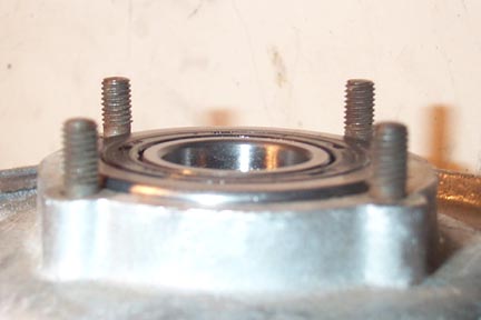
Start by heating the casing a little with a blowtorch. This will expand the aluminum and make the bearing fit in more easily. Fit the bearing with the stepped side towards the casing and the oil seal visible from the outside. Use a hammer and a large socket or a flat plate - be sure if you use a socket it rests on the outside rim of the bearing. Bang it in until it will not move in any more.
Once the bearing is tight against the casing you can install the single thin sheet metal plate, and then the thick metal retaining plate. The thick retaining plate has a small curve to it. Make sure the curve is facing the bearing, fit the four lock washers and nuts, and tighten them down.
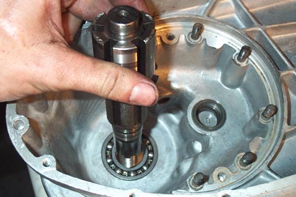
Flip the casing over so you can get to the gearbox side and start installing the components. I start with the rear axle shaft without the spider installed, but some people like to install the spider first on a work bench and then install the complete unit as one. Have a look at the rear axle before you install it and you will see that there is a hole drilled all the way through in the splined sections where the free gears run. Mark its location for later when the spider is installed. All you need to do is fit the axle and give it a few taps from a hammer and wood block, or a rubber mallet and it should go right in. Make sure it is in as far as it can go by checking that the axle is tight against the rear bearing.
The way the spider stays where it should when you are driving is by a single spring and two ball bearings on either end. The spring runs through the hole in the axle you marked earlier and the ball bearings are forced into notches on the spider legs. As you change gear, the spider starts to move, the ball bearings are forced against the spring, and then they pop back out into the next notch in the spider leg. The bottom side of the spider has two legs that are bevelled unlike the others. These are to aid installing it over the bearings which are trying to move out.
To fit the spider you first need to set the spring into the axle hole, and the two ball bearings on either end. Use a little grease if necessary to hold them in place.
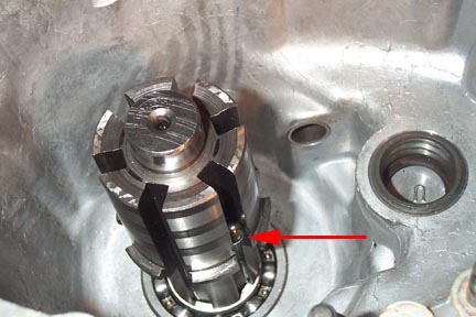
Place the spider on the shaft making sure the bevelled leg ends are in the same grooves as the ball bearings. Then push down hard and it should compress the ball bearing spring and drop firmly in to place. I always leave the spider in the first gear position for reasons that are clear later on if you have an all in one external actuating arm. This means that the spider legs are flush with the thick part of the axle as shown above.
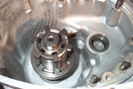
The selector arm can now be loosely fitted to the spider. It has two small rotating blocks on the end, which slide into the groove in the spider. Make sure the arm is installed so that the single bolt hole has the threads towards the rear hub.
On the outside of the casing above the rear wheel, slide the gear selector splined shaft into the casing. With one hand inside, make sure the shaft goes into the selector arm hole. Depending on your model, the selector arm may be a single piece but the one on this casing is a two piece unit. If it is a one piece unit you should probably fit the rear hub to make sure the gear selector arm doesn't hit the rear hub rim when the bike is in first gear. If it is a two piece like the one shown above, the arm will be adjustable and you can fit it so it doesn't hit the rear wheel before you complete the rebuild.
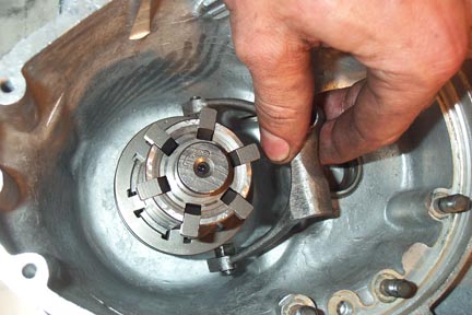
Once you are happy with the placement of the gear arm on the outside of the case, fit the single selector arm bolt and tighten it down with a socket. I move the spider through the gears at this time to make sure each one selects properly.
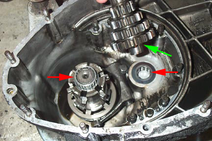
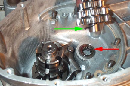
The small roller bearing (red arrow) can now be fit into the casing followed by a small gear cluster shim (green arrow) and the gear cluster itself. There is a special tool to remove the metal outer which is a press fit into the casing, but unless the play between the new roller bearing and the outer is obviously suspect, it is easier to leave it in place. I also found a difference between my new Indian casings which came with this piece installed, and my old Li125 Special casings. The new casings had a small lip which set the gear cluster further off the casings. I was worried this would misalign the free gears and the gear cluster but it ended up not being a problem. After asking a few questions I found that once the clutch is installed the gear cluster shaft is pulled tight to the gearbox end plate anyway, and doesn't really ride against this lip - the bearing is just there to locate it and spin.
Now start adding the free gears in the same direction you took them off. Make sure each gear interfaces well with the gear cluster. You may have to rotate them slightly to drop down over the shifting spider.
Fit first gear with the kick starting ring facing you. This is followed by a new axle bearing shim, and the new roller bearing at the end of the shaft. Once these are all installed, fit the single large gearbox shim which fits in the groove at the inside of the first gear piece (not shown installed, but it goes where the blue arrow notes). This shim may need to be replaced later with a thicker one, but unfortunately the only way to tell is to build the gearbox and then measure the tolerance.
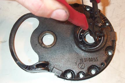
The gearbox backplate has a pressed fit ball bearing which supports the end of the gear cluster. Have a look at your bearing and see if it worth it to you to replace it. Since I was building a non-stock motor I replaced mine to be safe. To replace the bearing, remove the retaining circlip and bang the bearing out from the other side with a suitable sized socket. To install the new one, flip the backplate over and bang the new one in until it is flush with the inside lip. Refit the circlip and the back plate is ready to install.
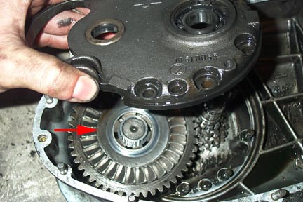
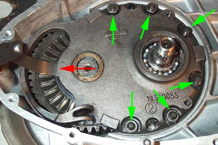
Before fitting the backplate make sure you have remembered the small roller bearing at the end of the rear axle shaft, and the important gearbox shim. Then carefully lower the backplate into position and push it down until you can see enough thread on the six casing studs (green arrows) to get the nuts started. Fit lock washers to each stud and then add the nut. Start tightening the nuts one at a time and only about a turn at a time. You are trying to set the backplate down so that the backplate bearing is forced onto the gear cluster in a level manner. As you tighten the nuts check to make sure the backplate is moving equally down on each side and that it is not racking in one direction or another. Once it is fully down, tighten all the nuts and either fit the rear hub and tighten it fully down, or fit a small spacer tube instead of the rear hub and also tighten it down. This is required because it makes sure the rear axle is absolutely tight against the bearing, so you can get an accurate reading of the shim tolerance noted below. Now get a set of feeler gauges to measure the tolerance between the backplate rim and the gearbox shim. Be sure you are getting the feeler gauge right in against the backplate rim where the red arrow is shown above. Anywhere between 0.30 and 0.07mm is within tolerance. If it is beyond this range you will have to remove the backplate and fit a thicker shim. Unfortunately the only way to measure the tolerance is with the backplate totally torqued down, so this may be a frustrating process. I usually have a couple of difference thickness shims on hand (these can be ordered from your scooter shop), and once I make the first measurement, a little math can work out the one you need. Next Section --> |
|||||||||||||||||