|
 |
 |
 |
 |
 |
 |
||||||||||
Vespa KitsSmall Frame: Large Frame: Installations: Malossi 210 Install |
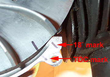
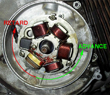
Vespa P200/PX200 - Malossi 210 installThis section goes over how to install the Malossi 210 kit on a PX200 or P200E. This section starts after the cases have been ported and the original barrel has been discarded. Five things are very important to make this kit run well. (1) Porting the cases. This really unlocks the power of the kit. If the cases are not ported you'll still get a faster bike but it will the kit won't perform as well as it could. (2) Re-profile the stock cylinder head. The compression ratio is slightly changed, but more importantly the kit has a larger diameter than the stock barrel bore, so your stock head either needs to be modified by a scooter shop to suit a 210 kit, or you can buy a new modified head from a scooter shop like Taffspeed. (3) Check the piston/head clearance. This is the distance between the top of the piston at top dead center (TDC) and the piston head at the circumference of the barrel where the clearance is the closest. (4) Changing the main jet in the carburetor. Since the bike can now burn more fuel because of a more efficient cylinder the main jet must be changed to allow that extra fuel to come through the carb. (5) Changing the stock timing. The Malossi kit requires a slightly different timing point compared to a stock 200. The Malossi requires 18 degrees BTDC compared to the stock 23 degrees BTDC.
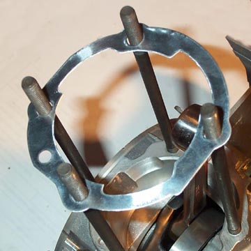
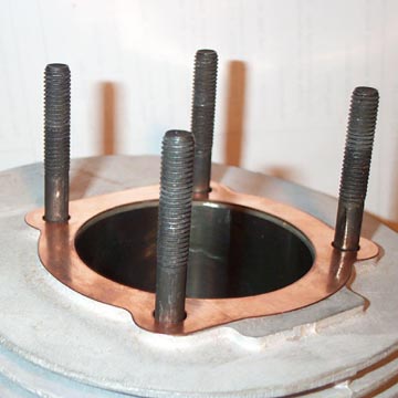
The first step is to fit the special Malossi base gasket to the casings. Make sure the cut outs in the gaskets align with the porting changes to the cases. The gasket will slightly overlap the existing transfer ports and this is OK as the barrel transfers fit the gasket exactly.
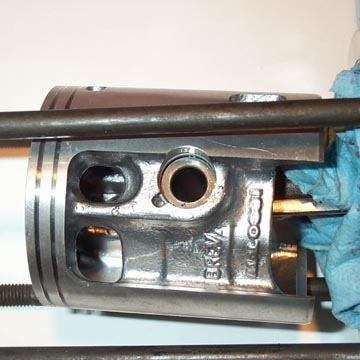
Fitting the piston is very similar to any other Vespa piston except the wrist pin circlips are little wire deals that are a bit of a pain to fit. Lube up the new Malossi small end bearing with two-stroke oil and fit it to the small end of the con rod. Then fit the wrist pin to one side of the piston and slip the piston over the con rod and push the wrist pin through. You may need to carefully tap it in to position - if so just hold the piston in place with your hand while you tap. Fit the wire wrist pin clips at either end of the wrist pin. We found that these were hard to fit but a pair of needle nose pliers was a great help. The wire clips must be fully in the grooves in the piston at either end of the wrist pin. The piston can only be fitted one way for the piston transfers and barrel transfers to align properly. Above the piston is shown from the side with up being the same as when the engine is fitted to the bike.
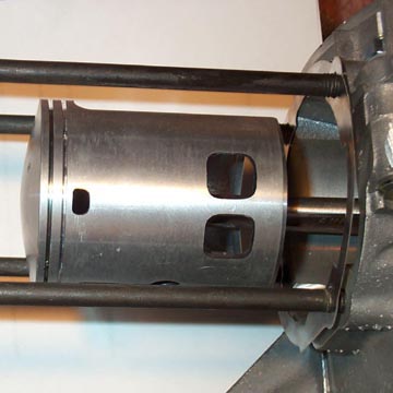
Above is another shot of the piston from above showing the correct orientation in relation to the casing. This is the side facing up. We did not fit the piston rings yet because the squish band still needs to be checked and it is far easier to do with the rings not installed. Lubricate the bore of the barrel with two stroke oil and slip it down over the studs. Now the piston should rotate up and down in the bore when the flywheel is turned.
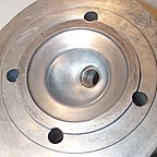
Re-profiled Head: The Malossi head is basically a stock head which has been machined to have an internal diameter which is 1mm larger than the new Malossi barrel bore (68mm) and has had a change in the combustion area. If you were to fit a stock P200 head to this kit the piston could possibly touch the lip at the head...which would be bad. Above on the left is a shot of the PX200 head which has modified for the kit vs. the P200 head on the right which is stock.
Before installing the head make sure you fit the special copper Malossi head gasket. Once both are in place, fit a washer, lock nut, and nut to each stud, and torque up the stud nuts in a cross pattern so the head does not warp. The correct torque is 20 - 22 ft/lbs. Checking the piston/ head clearance: The point to all this is to check the clearance between the outside edge of the piston and the inside face of the head. When the motor is in motion the piston and con rod actually stretch from the deceleration when the piston is coming towards TDC. If the clearance is too tight at the head there is a possibility of engine damage.
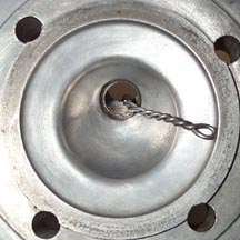
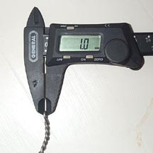
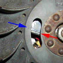
The easiest way to check this clearance is to get a thick piece of solder and twist it into an 'L' shape. Solder is very soft metal so it can be compressed into shapes or squashed. Make it large enough so that it can reach the cylinder wall (as shown above on the left) if it is stuck through the spark plug hole. When it is touching the cylinder wall turn the engine over one revolution. It may get difficult toward TDC because the solder will be getting compressed between the piston head which is what we want. Take the solder out and use calipers to measure the area that was compressed (as shown above on the right). It should be a minimum of 1mm. If not get hold of a second base gasket and install it with the original base gasket. This should raise the barrel slightly and increase the dimension. Bolt it all back together again and re-check the squish clearance.
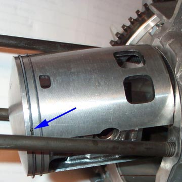
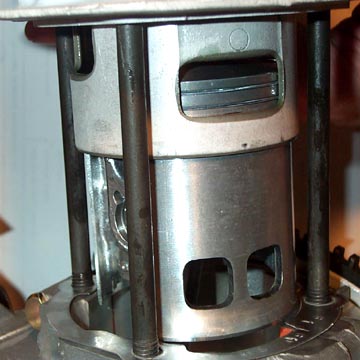
Once everything looks good, remove the barrel in order to fit the special Malossi piston rings. These are slightly bevelled on the upward face towards the inside circumference so they will only fit in the piston grooves in one direction. If they stick then take them out and flip them. The trick to getting them in properly is to stretch them over the outside of the cylinder and slowly slide them down the outside of the piston. In each groove there is a locating pin (arrowed above) which makes sure that the ring cannot spin and get fouled in a cylinder transfer.
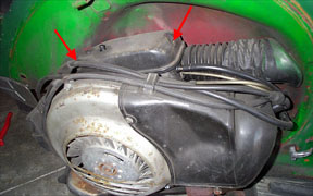
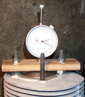
The barrel can now slide down over the piston. Take care to make sure the ring gap is properly located on the groove pin. Compress the ring with your fingers and slide the barrel down carefully over the piston. You can check the rings through the barrel transfer to make sure they are in their grooves. Slide the barrel all the way down and turn the flywheel to make sure the piston is moving freely in the bore. If you have a PX200 go ahead and fit the copper head gasket, put a washer, lock nut, and nut on each stud and torque up the stud nuts in a cross pattern so the head does not warp. The correct torque is 20 - 22 ft/lbs. If you have a P200 leave the head off because it will be necessary to time the bike with a dial gauge. Changing the main jet in the carburetor: Malossi recommends a 130 main jet to replace a standard 116 jet on a P200 and an NGK B8ES spark plug. This is a good start, but please note that depending on the other specs of your motor (expansion pipe, crank timing, carburetor, etc) you'll need to do a little experimenting. Replacing the plug is a simple matter of unscrewing the old plug and dropping the new one in. The main jet is located within the carb body at the end of a three part brass jet assembly. Remove the right hand cowling to get access to the carb box and remove the screws arrowed in the picture below.
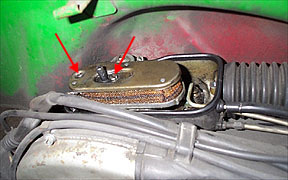
Once the carb box top is off the air filter will be exposed. There are two flathead screws which hold the filter to the carb body which need to be removed. They are arrowed in the picture below.
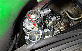
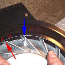
With the filter off the tops of the jets are visible. Remove the largest one (arrowed below) by unscrewing in a counter clockwise motion.
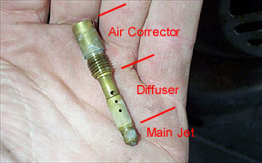
The jet is made up of three parts and the main jet is the small tip of the assembly. To remove it just poke a wire or something through the hole and pull it from the diffuser tube. This is just a friction fit and should pull out pretty easily. Fit the new jet and refit the jet assembly in the carb body. The orientation of the jet does not matter so the hole can point any direction. See below for a detailed view of the main jet assembly. |
|||||||||||||||