|
 |
 |
 |
 |
 |
 |
||||||||||||
Vespa Pre 1979 Large Frame Engine WorkClutch Removal |
Older Vespa Clutch RemovalThe clutch on all large frame Vespas is located on the rear wheel side of the crankshaft. There is an access cover which can be removed while the engine is still in the bike. Although the pictures are all from a Vespa 150 Super, these instructions will be correct for all older large frame except for the GS150 & GS160. The pictures shown are of a motor removed from the frame. To remove the clutch you will need:
If you are going to replace the clutch plates you'll also need:
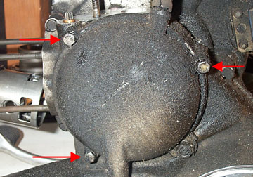
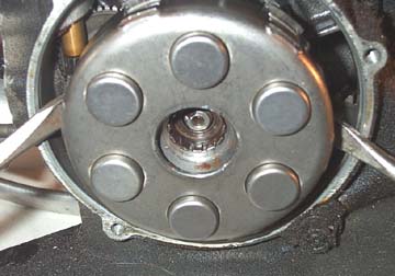
If your bike has seen some good use your
clutch cover will look somewhat like the one pictured above. It is a
good idea to run a rag over the area where the clutch cover seals
against the crankcase to make sure that no grime falls into the
transmission. To remove the clutch cover you'll need a 10mm socket and
driver. Do not confuse the end of the transmission input shaft as one
of the bolts. It is located right on the side of the clutch cover and
is much larger than 10mm. Once the three bolts (arrowed above) are
removed the clutch cover will come off with a small pull on the clutch
arm, away from the casing. There is a small brass plunger which may
fall out so be sure to save it for later.
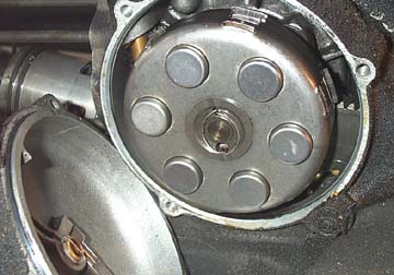
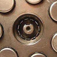
Above is a shot of the clutch with the
cover removed. The clutch is actuated by the small brass plunger (which
may or may not have fallen out of the clutch cover) pushing on the
center plate of the bell housing. The center plate has a small bent
piece of wire which secures it over the clutch retaining washer and
nut. To remove it use a pair of needle nose pliers to push both ends
toward the center of the plate.
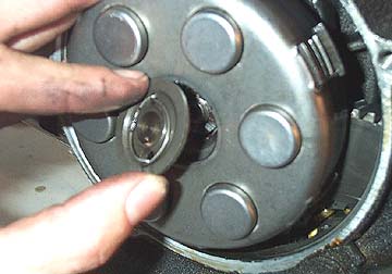
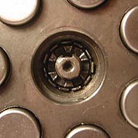
With the center plate removed, the nut
and retaining washer will now be clearly visible. The way the retaining
washer works is that it has many metal tabs around the perimeter, and a
single tab in the center which slides into a slot in the crankshaft.
When the castelated nut is torqued down, one of the tabs will usually
line up with a 'valley', and is bent into the lower part of the
castelated nut. This stops the nut from loosening under turning from
the crank and/or clutch.
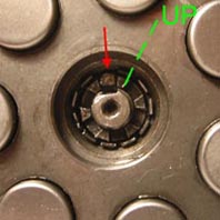
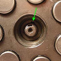
Firstly, if the end of your crank looks anything like the one pictured above, you may want to consider a more comprehensive rebuild. These pictures were taken with an old crank/clutch combination out of the bike to show the detail of the nut/washer relationship as it is very important. In the first picture above, the red arrow above shows the tab bent over in the 'valley' of the castelated nut. You can also see the slot in the crank end which forces the washer to turn with the crank rather than with the nut. The green dashed line is there to show how to orient the clutch before you remove it. There is a woodruff key set in the crank end which is hidden but can drop into the gearbox unless it is facing upwards. The green line should face directly up even though it is off by 15 degrees or so in these shots. The second picture above shows the tab bent back in line with all the others which will allow the clutch nut to be loosened and removed. I use a small flat head screwdriver to get under the tab and pry it back. Before loosening and removing the clutch nut the clutch bell has to be stopped from turning. On most bikes the clutch will not need anything more than a rag and a tough grip by yourself or a helper. If it still wants to turn with the crank here are a few things you should NOT do:
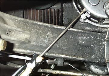
Of course Vespa has a tool which locks
the clutch in place and while you could make one, I have found that
with a little care, the following method works quite well (thanks
Matthew). I thread the lower 10mm bolt almost all the way back into the
casing by hand and get a small flathead screwdriver to wedge into one
of the clutch bell housing slots. If the screwdriver is long enough the
handle will then jamb on the swingarm as you increase the pressure on
the clutch nut.
This system seems to work well and doesn't elongate or put a slot in the clutch bell housing because the force loosening the clutch nut is slowly applied. Please note that this is not really the correct way to do it but it has worked for me on the few times a rag and a strong grip hasn't been successful. The shot above is actually a P200 engine but the idea is the same for the older version. Try it at your own risk...
Now use the clutch nut removal tool and
a driver to remove the clutch nut. This should always be replaced along
with the retaining washer as they are cheap and the more times they are
used the more rounded of the nut edges get which will make it harder to
loosen in the future. When the clutch nut is removed the retaining
washer can slide out of the recess. In the second picture above you can
now see the woodruff key slot in the clutch drive assembly, which must
face directly up before pulling the clutch off the crank.
The clutch can now be pulled free using
only your hands. If it is stubborn you can use screwdrivers to lever it
off, but if it doesn't move with minimal force, use a rag to protect
the gasket surface which they may damage.
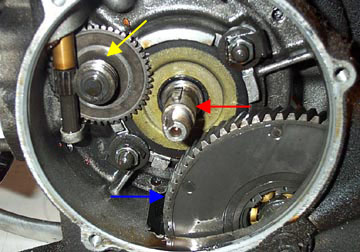
The clutch has been removed on the shot
above along with the oil mixer drive gear. This shot is from an
autolube Vespa 150 Super. If you are interested, the yellow arrow shows
the oil metering drive, the red shows the end of the crank, and the
blue shows the large helical cut primary drive gear.
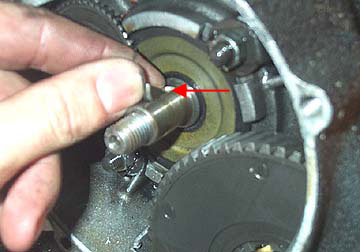
Once removed be sure to either remove the woodruff key (red arrow) in the crank or tape it in place. There is nothing worse than one falling into the gearbox making an hour long clutch replacement turn into a full rebuild (sorry for the blurry picture). Next Section - - > |
|||||||||||||||||