|
 |
 |
 |
 |
 |
 |
||||||||||
Vespa Semi-Hydraulic Front Disk InstallationThis page shows how to install a
semi-hydraulic front disk brake on a 20mm front axle type fork. If you
have a 16mm axle then you'll either need to get the old kit, or replace
the forks with the 20mm axle type. This project was going in a 1979
P200 so the forks had to be changed.
If your bike doesn't have the 20mm axle
forks you'll need to drop the old ones out of the frame. Here's a page on how to get them out of
the frame and also shows the reinstallation which applies to either
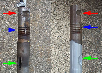
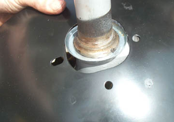
forks. Something to be aware of is that the older style forks that have
a single push in steering lock with a separate ignition key have a
different way of locking the forks. On the left above is a standard
16mm P200 fork tube top. The pinch bolt cut out (red arrow), and washer
slot & threads (blue arrow) are the same in both. The area which is
different is the steering lock recess. We modified the P200E lock to
fit the new style but it was a very labor intensive job and involved
installing a single steering lock and ignition switch where the old
steering lock switch used to be. Instead I'd recommend test fitting the
new forks with bearings but loosely tightened down. From there you can
determine how to modify the fork tube so that the existing lock pin
will fall into a hole that can be drilled in the fork tube.
The first thing to do is make sure all
the parts fit. With so many manufacturers making scooter bits it helps
enormously to dry fit everything before getting half way through the
project and run into a problem. We decided to change the forks out and
also replace the existing shock with an aftermarket shock from Biturbo.
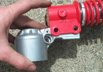
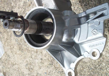
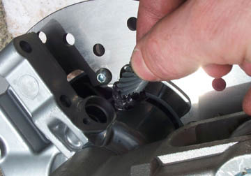
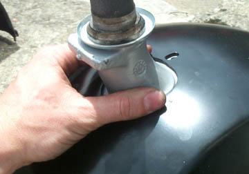
We found that the Biturbo shock needs a
little grinding to clear the speedo drive as shown above. All the other
parts fit together with no problem.
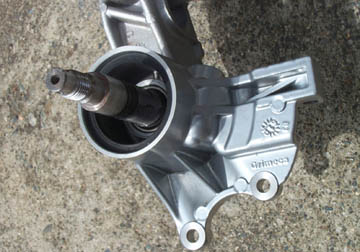
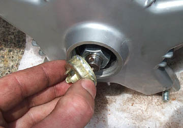
The first step is to fit the washer on
the bare 200mm axle. Either way is fine.
Take the semi-hydraulic disk brake kit
and remove the caliper from the back plate. Two single bolts hold the
caliper in place. The caliper should come off along with the hydraulic
line and the remote reservoir. This allows the back plate to be split
from the rotating hub and disk. Some kits are shipped with the disk
attached and others are not.
Slide the single back plate casting down
over the axle. For now it doesn't matter which way the caliper bracket
part is facing.
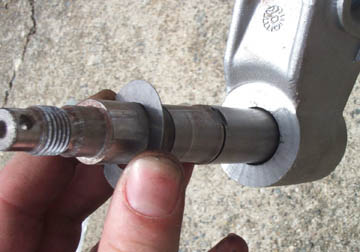
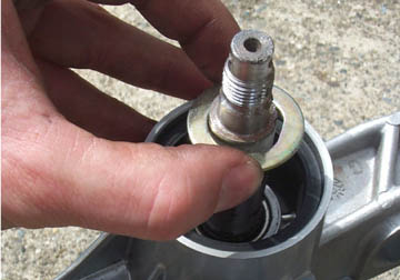
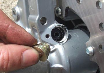
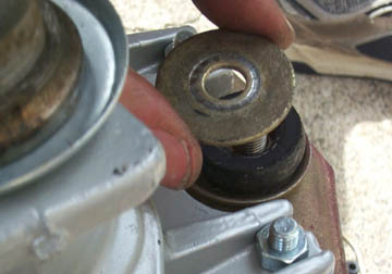
Have a look at the axle and the special
washer and you'll find that it is not totally circular. There is a
flattened face to both. Drop the washer down on the axle and make sure
the flat part of the washer is in line with the flat part of the axle.
Find the single retaining clip and
expand it over the axle. Slide it down over the axle until it is flush
with the washer you just fitted. Make sure when you release it that it
falls securely into the groove in the axle.
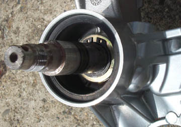
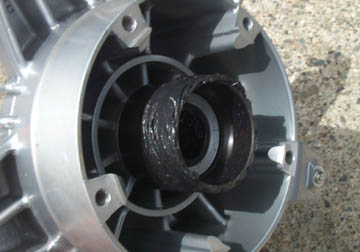
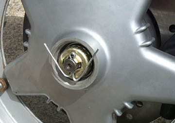
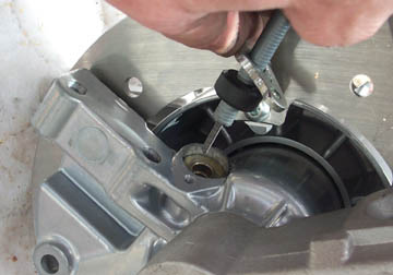
Above is a shot down into the hub for
reference. This is a very important part of the installation so it is
important to get it right.
Go back to the hub and grease up the
speedometer drive. The hub we had came with the disk not attached but
had all the attachment hardware included in the kit.
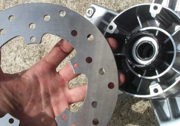
Take the disk and inspect the surface.
On one side there is an arrow noting which way the disk should rotate
when the bike is moving forward. Make sure you install the disk with
this arrow facing the correct way. Use the hardware included with the
kit to attach the disk. This hardware is a very close fit to the fixed
hub when the disk is rotating so it is important to use what is
included in the kit.
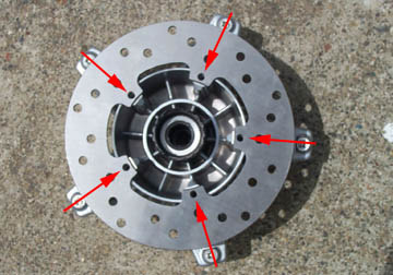
Above is a shot of the disk with the 5
mounting points arrowed for reference.
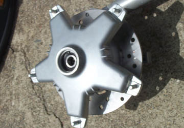
Set the hub and disk down over the axle.
It may need a bit of wriggling around to have it drop all the way on
the axle.
Fit the single nut and tighten it down.
You may want to leave this step until the forks are in the bike as you
can get more torque from your racket since the forks won't move on the
workbench. Either way, be sure to fit the nut cage....
...followed by a new split pin to stop
the nut from loosening while the bike is in motion. The ends can be
bent further to allow the small hub cap to go on over it.
Grease the speedo drive and fit it into
the drive hole. It helps to rotate the wheel when inserting it in the
drive hole.
Follow this with the thick metal
retainer.
Finally get the speedo cable from the
drive end and slide the outside retainer cap followed by the rubber
bung. Push it all into the drive hole and secure the outside cap with
the single bolt. Test the cable to see that the top end rotates when
the wheel is rotated.
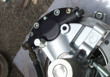
Now the caliper can be reattached with
the two bolts with slip washers. If the caliper will not fit over the
width of the disk, you can carefully force the caliper more open with a
flat head screwdriver. The hydraulic line should exit the caliper as
shown above and the remote master cylinder can just be left hanging fro
the moment.
Fit the bottom of the shock to the
stationary back plate. Use bolts with lock washers or nylock nuts.
These are the only thing holding the fork to the back plate.
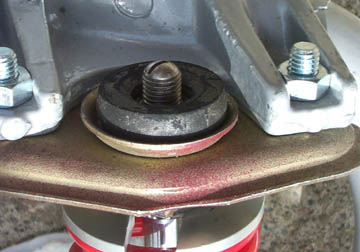
The top and bottom end of the front
shock is the only thing that stops the back plate from rotating. At the
top end, fit the metal retaining plate to the forks with two bolts,
nuts, and split washers. The top of the shock has a single rubber ring
as shown above.
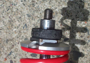
Push the top of the shock through the
mounting bracket, fit the dished washer, followed by another rubber
ring.
Follow this with a single thick metal
washer and loosely fit the lock washer and single nut. If the shock
shaft tries to rotate when you turn the nut, just move on to the next
step.
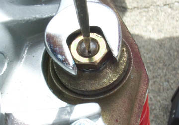
To fully tighten the nut down, use a
flat head screwdriver to stop the shaft from rotating while using a
wrench to tighten the nut.
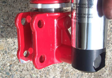
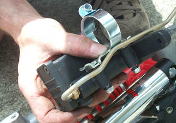
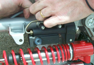
Find the remote master cylinder
installation hardware and bolt it to the master as shown above.
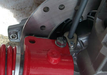
The remote master cylinder fits on the
fork tube just below the front mudguard mounting bolt. The hydraulic
line is a close fit but leave a little gap between it and the mount.
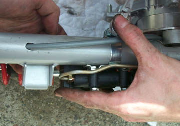
Here's a shot from above showing the
speedo cable exiting the lower hole and the master cylinder bolted in
position.
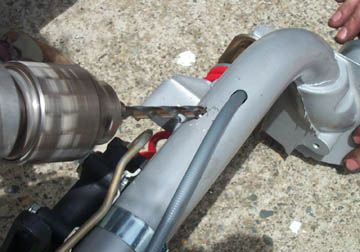
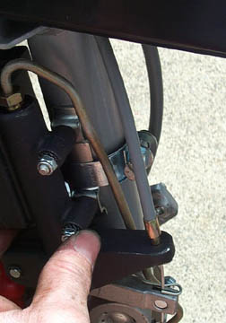
The only problem with the 20mm forks we bought was that they
are designed to have a hydraulic line that comes off the frame not
running down the center of the forks like a typical front brake cable
would be run. Because of this we had to drill another hole for the
front brake cable. Make sure you drill it at an angle as shown above.
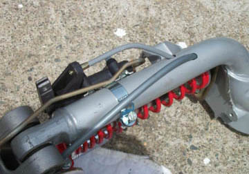
Now the shortened front brake cable can be run down to the
master cylinder and correctly slide into the plastic of the housing.
The final step before putting the forks back in the frame is
to fit the front mudguard. It will fit over the dust cap and bearing
race but it's like a giant mind puzzle to get it on. Try rotating it 90
degrees.....
...and dropping it over the dust cap. From there align it
properly and install the three bolts at the top and the single bolt in
the shock side of the forks.
The final step is to connect the new brake cable to the lever and the master cylinder. Once it is connected at the lever end take up any slack in the cable. Install the return spring with the ends hooking the cable. Thread the cable over the nipple and tighten it down. With the bike on the stand, make sure the wheel turns without rubbing on the brake pads. Then try the brake and make sure it engages evenly and smoothly. From here, replace the rim and tire and take it out for a test drive. Next Section --> |
||||||||||||||||
BrakesGeneral Hydraulics Vespa Semi Hydraulic Disk Installation Lambretta ScootRS Disk Installation - Part 1 Lambretta ScootRS Disk Installation - Part 2 Resources |
||||||||||||||||