|
ScootRS Lambretta Disk Brakes Installation
- Part 2
Now that the bottom part of the disk
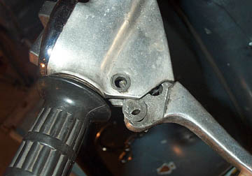
brake is installed, we can move up to fitting the master cylinder. The
entire aluminum casting that holds the headlight / horn switch and the
front brake lever must be replaced. Remove the single pivot bolt and
remove the front brake lever. The cable can also be pulled from the
frame.
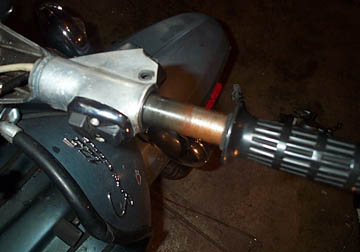
The throttle tube must also be removed.
The throttle wheel has to be disconnected from the tube end to remove
it. Lambretta had two systems for keeping this wheel on. Early models
have a brass wheel which is held on by a single bolt which will need to
be removed. Later models have a plastic wheel with a metal dowel
through a hole in the wheel and throttle tube. This needs to be tapped
out with a punch. Once the throttle wheel is removed the tube can be
removed by sliding it out of the headset. Be sure to note the order of
any washers between the grip and the aluminum casting.
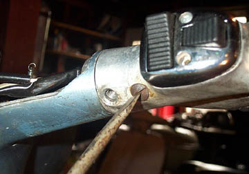
The aluminum casting for the handle bar
switch and brake lever is held in place by two screws in the underside.
Remove these two screws, remove the switch connections at the main
headset electrical block and unscrew and remove the switch from the
casting.
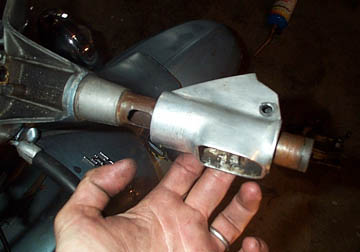
Now the aluminum casting can slide off
the handlebars and be replaced with the new casting from ScootRS. Refit
the two securing screws, refit the handlebar switch, slide the throttle
tube through, and reconnect the throttle wheel to the end.
With the main parts of the top and
bottom in place it is time to run the hydraulic line. I found it much
easier to run the line with the horn cast removed. To remove the horn
cast, there are two screws just under the headset on the inside of the
legshields that must be removed, followed by two more lower down the
inside of the legshields, two bolts which pass up from the mudguard
into the bottom of the horn cast, and two Allen head bolts hiding under
the horn cast emblem. With these removed, the horn cast will lift off.
Be sure to note how the rubber trim is located so it can be put back
correctly when finished.
The kit came with a rubber hose but I
bought a 36" long braided steel hose instead. They can be bought at
motorcycle chopper type stores in a variety of lengths and the end
fittings are bought separately so you can make up any hose
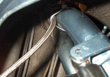
configuration you want....or stick with the rubber one. Basically it
runs down the right hand side of the frame tube and out on to the forks
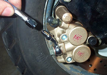
at the bottom. The hose ends at the caliper and master are held in
place by a banjo bolt that has a fluid hole down the middle. Place a
single copper washer on the bolt, push the bolt through the hose
fitting, and fit another brass washer on the other side before
tightening the bolt into the caliper/master cylinder.
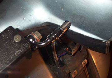
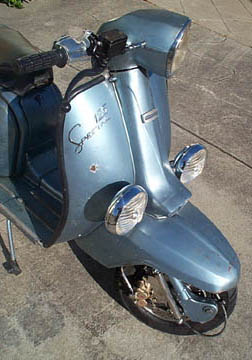
At the top end I connected the hose as
shown above. I ran the hose above the headset bottom so that I wouldn't
have to drill a hole in it. This way I'll have to cut a notch in the
headset top only. You can either drill a hole in the lower or drill a
hole in the upper - it is up to you. My thought was that if I ever
removed the disk from this bike, all I would have to do is find a new
cover which is a 10 minute job to replace vs. replacing the lower.
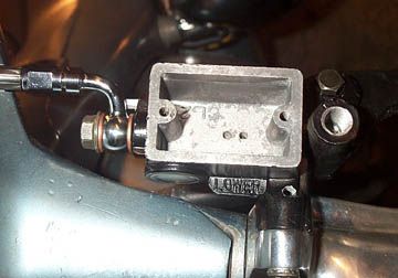
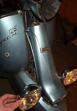
The bottom end is a similar fitting.
Tighten everything up and...
..use ties to hold the hose to the upper
part of the forks. Move the headset from left to right to make sure the
hose doesn't rub on the mudguard. If it does, add another tie to hold
it away from the wheel and the mudguard.
Depending on where you decide to run the
hose, carefully mark and remove material until the headset top can go
back in to place properly. After the hose is properly routed you can
replace the horn cast if it was removed during the process.
To add hydraulic fluid to the system,
open the top of the master cylinder by removing the two screws on the
top cover. Remove the plastic and rubber seals. Use a plastic drop
cloth or something similar over your paint work. Brake fluid will
remove paint, but it is not immediate. If you do spill any on your
paint work remove it immediately with a cloth and rub down the area
with warm water and soap. Fill the master cylinder halfway up with DOT
3 or DOT 4 brake fluid from a sealed container.
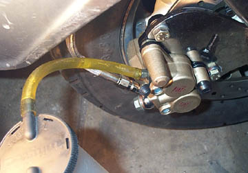
At the bottom end of the system, loosen
the small bleed bolt which has a little rubber cap on it. Either
connect a long length of plastic hose to the bleed nut and route it
upwards so that the fluid will not drain, or use a bleed system like
the one above that uses a vacuum to help move the hydraulic fluid
through the hose. At the handlebar, carefully start pumping the lever.
Make sure you add more fluid as the level will start to drop as the
fluid enters the hose. Soon you should start to see fluid and bubbles
coming out of the bleed nut. Keep pumping and adding fluid until there
are no more bubbles coming out of the bleed nut. Now carefully tighten
the bleed nut and disconnect the bleed hose. Top up the hydraulic fluid
in the master cylinder (if necessary) so that the level is visible
through the small sight window. Refit the top of the master cylinder
and give the lever a squeeze. You should have a working brake system.
If the lever goes all the way to the grip with no action at the caliper
you either have a leak in the system or air in the hose. Repeat the
bleed process until the brake caliper grabs the disk.
Take the bike out for a test drive and
make sure the brake grabs consistently when the lever is in the same
position on each pull. If there is rubbing of the caliper on the disk
when the lever is all the way out, you can open the bleed valve just a
bit, pull the lever to where you want it to grab, and without letting
go of the lever, tighten the bleed nut back in. Be sure all nuts and
washers (especially those on the axle) are tight. Once you are happy
that the system is working well and everything is double checked and
tightened take it out for a longer drive.
End of Section -->
|
|