|
 |
 |
 |
 |
 |
 |
||||||||||||
Vespa Post 1979 Large Frame Engine WorkDropping the engine |
Removing the engineThere are many jobs that can be done with the engine in the frame, but a full rebuild will be 10 times easier with the engine out of the bike. This section will show how to remove a large frame engine from any year so that it can be split on a work bench. Depending on what bike you have, the pictures may look different than the P200 engine in this section but it should be similar. To remove the engine you'll need:
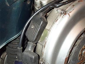
(1) General: The first step is to remove the engine side cowl and get the bike up on its stand. Wedge something like a jack stand or a piece of wood under the rear of the frame to get the rear wheel just off the ground. On a P200 you can remove the snap in plastic bumper so that it doesn't get damaged. (2) Drain the oil: Draining the oil is not absolutely necessary, but there are some positions the engine may be in that will cause oil to leak during the removal process. Click here for a step by step instruction to remove the oil. (3) Disconnect the electrics: There is a small junction box located on the flywheel side casing of the motor that connects the engine electrics to the frame as shown below.
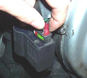
Remove the single screw and open the cover to expose the wiring. There are many connectors that are separated in slots in the plastic casing. Pull these out of the plastic junction box and grab a piece of paper and pen to right down what colors connect. This is very important as it is easy to forget when the engine is put back in 2 months later. Usually one wire from the frame will also go down to the CDI or coil. On a P200 this is the first green wire on the CDI box. Lift the rubber boot going to the external CDI box to expose the 4 wires which plug into it. Remove the first green wire and pull it out through the top of the rubber boot (see below).
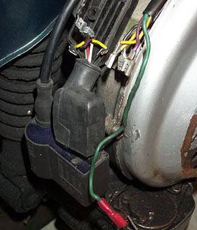
Follow the wiring to where it comes out of the frame. All these wires should now be disconnected as shown below
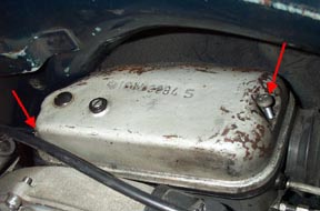
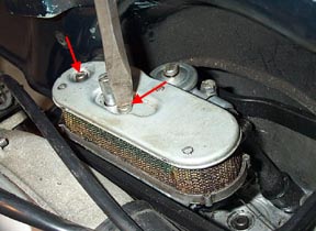
(4) Disconnect the fuel line (& oil line on some models): Turn your fuel valve to off. On all vespas this should be the far left position. Locate the carb box and remove the two screws on the cover as shown below.
Once the cover is removed the air filter must be removed to get better access to the fuel line connection. You can also remove the rubber bellow between the carb box and the frame by simply pulling it off at each end. This will give you better access to the fuel line. The filter is removed by removing the two flathead screws as shown below.
With the filter out of the way, the fuel line is visible going into the carb (red arrow below). I always put a pipe clip over mine to replace Vespas wire clip - either way remove the clip and force the fuel line off the carb stub. If this is very tough you can use a 10mm wrench on the fuel stub itself. It will then be easier to pull the stub from the line. Don't worry if a little gasoline spills from the line - it is just the remainder of gas left in the line and should stop quickly. Once removed push it through the bottom of the carb box. The bellow opening in the frame is a great place to stuff the fuel line back into to keep it clear of the engine.
This bike has had the oil pump removed, but if you have one, the oil line will also need to be disconnected. It is usually easy to slide off the oil pump metal tube just outside the carb box. Stuff the end into the frame bellow hole, as it is higher than the oil tank and will stop the oil flow.
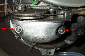
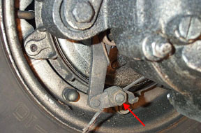
(5) Disconnect the gear selector: The gear selector can come off in one piece with the gear cables still connected. You ma or may not need to remove the kickstart because on some models the kickstart bolt will hit the gear cable adjuster and stop the selector coming completely off. Start be removing the selector box cover which is retained by a single screw at the base of the fan cover (green arrow below). Then remove the two 11mm nuts that hold the selector on (see red arrows below).
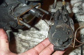
At the headset, turn the gear selector grip all the way to 4th gear and the gear selector should push itself out from the engine casing. You may get a small amount of residual oil leaking from the join, but it will stop quickly. Once the gear selector is in 4th gear you should be able to pull disengage the small arm on the end of the drive axle and pull it clear as shown below.
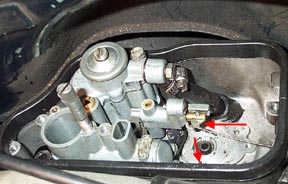
(6) Disconnect the control cables: The clutch, throttle, choke, and rear brake cables must also be disconnected. Let's start at the carb box first. The choke cable is a small wire cable looped over a hook on the carb (upper red arrow below) and the throttle slide is next to it (almost visible with the 2nd red arrow below). This shot still has the fuel line even though it should be disconnected by now.
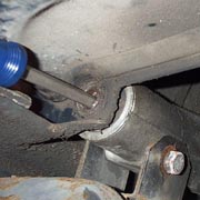
Unhook the choke cable and push it back through the carb box hole. Use the frame bellow hole again to keep it clear of the engine. The throttle cable has a a soldered nipple which has to be dislodged from the carb slide/oil pump end. Use headset throttle to open up the throttle, and then catch it with a screwdriver at a half open point and remove the throttle cable from the slide end. Push this back through the carb box and bend it up into the frame bellow opening. The rear brake arm is located just below the rear shock mount and has a single 13mm bolt with a hole through the center which holds the brake cable in place by compression. Loosen the nut on the outside face of the brake arm and the cable should pull through (see below). Once free, pull the cable out of the casing mounted cable adjuster and clear of the engine.
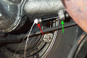
Lastly, the clutch cable needs to be disconnected from the clutch arm. Look underneath the engine on the bottom of the swing arm to find the clutch nipple and arm. There is a single nipple holding it in place with an 8mm outer and a 7mm inner (see red arrow below). Use the 8mm wrench to hold the outer, while using the 7mm wrench to loosen the pinch bolt. Once loosened it will thread off the cable and the entire cable can be pulled free of the casing mounted clutch adjuster (green arrow below).
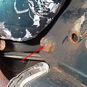
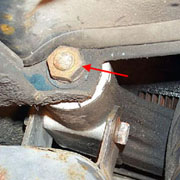
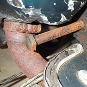
(7) Removing the main pivot bolt and rear shock bolt. The last two items that hold the engine in place are the rear shock connection and the main pivot bolt which passes through the swingarm and the frame. The shock bolt is usually the best to remove first (see below). Use a 14mm driver on the open side (red arrow), and a 14mm wrench on the hidden nut on the back side (green arrow). If you don't stop the back side from rotating the entire bolt will rotate rather than coming loose. Once removed, used a pair of vice-grips to pull it free. The engine should drop slightly until the rear wheel hits the ground.
The main pivot bolt has a hex head on the engine side and a nut and lock washer on the glovebox (60s bikes) or spare wheel side (70s-80s bikes). Use the 22mm socket to remove the nut. You may need to clamp some vice-grips to the bolt side to stop it from rotating. The nut and lock washer can be removed without danger of the engine falling out of the bike.
If you have really nice paint work it is advisable to put a rag between the cylinder and the frame, and another between the top of the muffler and the frame before removing the pivot bolt. To remove the pivot bolt I like to use a large flathead screwdriver. I have found that if you just pull the bolt out the engine starts to lean towards the left of the bike and makes it harder to get it out. It is much easier to have the engine lean to the right instead. To make this happen I drive the bolt through with a screwdriver and hammer. This way when the threaded end is pushed through the frame, the screwdriver takes the weight. I then use the vice-grips to pull the bolt out at the engine side.
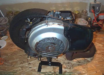
This then makes the engine lean over to the right as seen below. It is really helpful to have someone to help out because the engine/rear wheel, and muffler weighs about 90 lbs.
The gear cables now need to be moved clear of the exhaust and then the whole engine can be pivoted down and out of the frame. Push the rear shock back towards the rear of the frame to get it clear. From here you can get the engine up on a clean workbench and have all the space and light you need.
Next Section -->
|
|||||||||||||||||