|
 |
 |
 |
 |
 |
||||||||||
Electric StartAdding an Electric Start Engine: USA P Series Before Serial Number 34626 Adding an Electric Start Engine After Serial Number 34626 Making the Electric Start Work on a P Series Engine |
Adding Electric Start to a P Series Frame with an Electric Start Motor Already Installed.Many shops have been replacing engines in P series bikes with new ones from Italy or India and many of these come with electric start built in. Most shops I have seen just leave the electric start system in place but don't actually make the connections to make it work. Since you have it you might as well hook it up! You'll need:
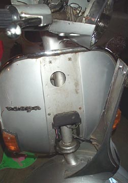
Remove the headset top by removing the 4 screws from the underside of the headset. Carefully loosen the speedometer connection to the speedo to free the headset top so it can be lifted away from the bottom, but don't disconnect any wires.
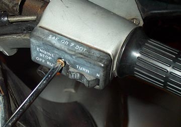
Remove the right hand side switch cover
by removing the single central Phillips screw.
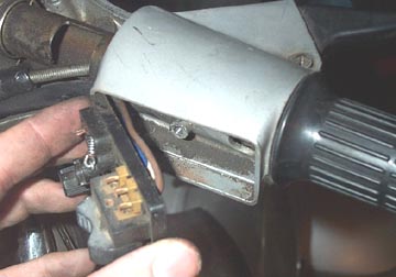
Pull the switch internal plate away from
the headset body. You can wedge something in between them if the wires
are very tight. It just has to be clear of the headset for the drilling
in the next step.
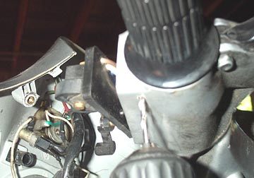
Place the electric start switch where
you want it and mark centers for the two small holes that need to be
drilled. Take a small drill (about 1/8" or so) and drill out both holes.
Then drill a larger hole in between
them. This hole must be large enough for the two wires that come off
the top side of the switch.
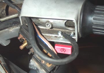
I used two small bolts with Nylock nuts
to hold the switch in place. The Nylock nuts are important because they
will never shake free. Cut the plug end off the electric start switch
before threading the wires through the large central hole and through
same hole as the switch block wires. Now you can put the handlebar
switch body back together.
Now a single 18 gauge wire needs to be
run through the frame from the headset to the rear. To make things
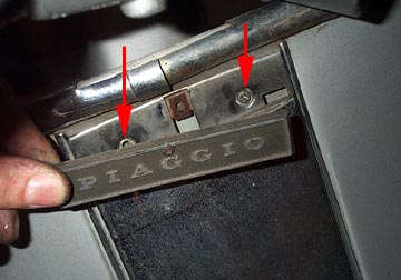
easier I removed the horn cover. To get the horn cover off, remove the
single screw holding the "Piaggio" sign just under the headset. This
will then allow you to get to the two hidden screws underneath.
Open the glove box to find the two
remaining screws on either side of the frame tube that hold the horn
cover in place.
The cover should now come loose but is
still connected to the frame by the two horn wires. You can either
choose to unclip these, or just pivot the horn cover to one side.
Now get a long length of 18 gauge
insulated wire and feed it down through the area shown in the headset.
It should pass by the steering bearings and go in to the frame tube.
With a little fishing you should be able
to get the wire down to the horncast junction box. From here pull it
through and then push it back into the frame to continue through to the
rear.
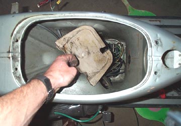
Remove the seat and gas
tank, and remove the plastic frame cover which is a press fit in
the metal bracing. If you have a helper it is very handy to have help
getting the wire from the horncast junction box back to the area under
the gas tank. Once you have it, pull it through and keep at least 24"
of wire free at each end.
The relay will be powered by a 12V DC
source from inside the headset. I used the white wire, but there are
many that would work. What you are looking for is something that
becomes "hot" when the ignition is turned on. The speedo light is a
good option since it is always on. Splice one lead from the starter
switch to the "hot" wire and connect the other starter switch lead to
the end of the wire that you just ran through the frame. This will mean
once the ignition is turned on and the button is pushed, 12V DC will
run through the new wire.
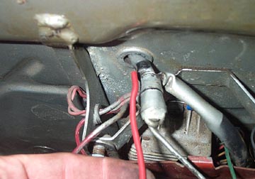
Pull off the left side panel to expose
the battery area. I found it easier to remove the spare tire to do the
next step but it is not required. Take a length of red 10 gauge wire
and push it through the hole in the frame where all the other wires go.
Cut it off so 24" or so is inside the frame.
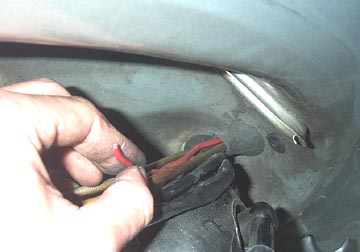
Run a second red 10 gauge wire from the
area under the gas tank and out to the engine side through the hole for
the wiring loom. Leave 24" or so inside the frame.
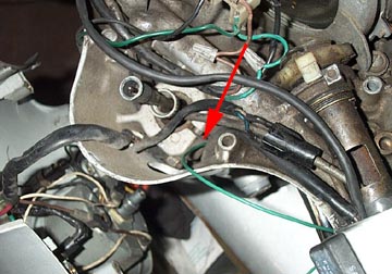
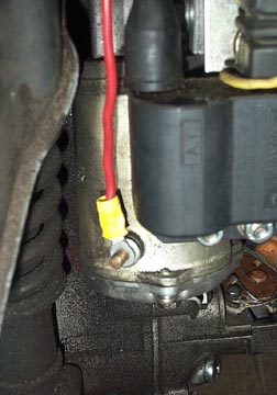
Pull enough length through so it can
reach the starter motor. Slide the rubber boot for the starter weather
seal over the wire and crimp on a connector with a hole in it at the
end. Look under the bottom of the starter and you'll see a lug coming
off the starter that is insulated from it. Run the red wire with the
crimped connector to this lug and tighten it down. Pull the rubber boot
over the connection to protect it from water.
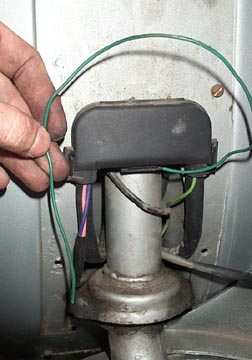
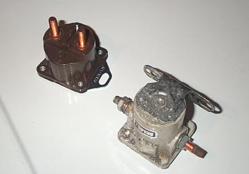
I used an automotive starter relay in
this bike because they had them in stock at Kragen and it would be easy
to replace if needed. The shot above shows two different relays that do
the same thing. A relay is basically a big switch which is activated by
a small electrical charge. In this case the 12V DC from the starter
switch activates a larger switch which can handle the amperage required
to run the starter without burning out. Most relays will have three
connections on them. The two large threaded connections are for the
load to the starter and it doesn't matter which red lead goes on which
connection. There is also a much smaller lug on the relay which is for
the 12V DC from the switch. Ground is usually attained through the
housing of the relay.
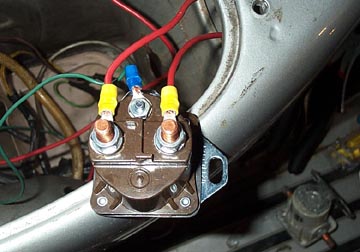
The shot above shows the correct
connections to the relay. The green wire from the switch is connected
to the small lug, and the two large lugs make the connection between
the battery and the starter. At this point, crimp on a final connector
with a hole in it to the battery lead. If you haven't already switched
the stock battery out for a 12v 9ah battery, now is the time to do it
before the starter is fully connected. Since the relay connections are
exposed, try clamping the relay to the frame for a test, making sure
only the metal body of the relay touches exposed metal on the frame.
Connect the battery, turn on the ignition, and push the starter button.
The starter motor should engage and start turning the flywheel.
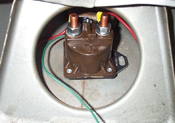
The final step once everything is working is to find a permanent location for the relay. I used the bolts for the helmet hook to hold it in position , yet it is still visible through the air intake hole under the seat. Another option could be next to or near the battery. Now that everything is installed you can replace the bodywork removed and start using the electric start feature. End of Section
|
||||||||||||||